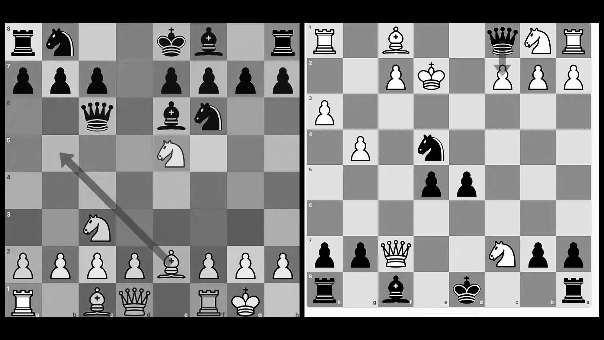
Planning a path past the signs instead of reacting to pillars
62 / 62 on 20 simulated obstacle fieldsA self-driving car for WRO Future Engineers 2026. It maps the traffic signs, plans a path for its own turning radius and follows it. In simulation it scores full marks in both challenges, parking included.
WRO Future Engineers, a category of the World Robot Olympiad, gives teams of two or three students aged 14 to 22 one job: build a small car that drives itself. It has to fit in 300 × 200 × 300 mm, steer like a car rather than turn on the spot, and do three laps of a 3 × 3 m walled track with nobody touching it. In the obstacle round, red and green signs stand on random seats, each to be passed on its own side, and the car ends the round parked between two magenta blocks.
I designed a car for the 2026 rules in CAD and code, and wrote it up as the public engineering repository that the judges score alongside the runs. My first version reacted to the nearest pillar, and it failed whenever a sign stood right where a corner ends. The car hasn't been built or driven on a real mat yet. In Webots, running its own unchanged code, the version that maps the signs and plans a path scored full marks on all 28 fields, parking included.
- 30 / 30
- on all 8 open-challenge fields, in 56–62 s
- 62 / 62
- on all 20 obstacle fields, 8 of them never seen while tuning
- 143 mm
- wide, narrowed from 196 mm to fit the parking lot
- 0
- laps on a real mat so far
Reading the rules before picking parts
The rule book decides most of the car before a single part is chosen. The track is a 3 × 3 m square inside 100 mm walls, cut into four straights and four corners. In the open challenge the inner walls move between rounds, so each corridor is 600 or 1000 mm wide. In the obstacle challenge every corridor is 1000 mm and the signs come from 36 cards drawn at random. Each round lasts three minutes.
I started from the score sheet, because it says what each part of a round is worth. An obstacle round tops out at 62 points, and 22 of them depend on the parking lot.
- Sections driven, 8 a lap24
- Three laps3
- Stopped in the finish section3
- No sign moved10
- Started in the lot7
- Parked fully and parallel15
| What the rules ask | What it forces on the design |
|---|---|
| Open challenge: three laps; the inner walls move between rounds, so corridors are 600 or 1000 mm | No hard-coded route. The car has to find the walls every lap. |
| Obstacle challenge: red and green signs on random seats; red is passed on one side, green on the other | The car has to choose a lane before a corner, not inside it. |
| Start in the parking lot (7 points) and park in it at the end (15 points) | A lot 200 mm deep, and a car counted as parked only if it is wholly inside |
| One switch turns the car on | One battery, even though separate supplies for logic and motors are the usual advice |
| Wi-Fi and Bluetooth off during a round | Everything runs on the car. No laptop in the loop. |
| A public engineering repository, judged alongside the runs | The design reasons have to be written down, not only the code |
Two references shaped the design. The WRO Getting Started guide answers the common questions: which camera height, which steering actuator, how to threshold colours. KMIDS-GFM's 2025 car, a past entry, showed that a mechanical differential and starting inside the lot were both legal and worth doing. Where the guide and the rules disagreed, the 2026 rules won.
Building a buggy from printed tubes
A WRO car spends three minutes brushing past walls and pillars. Its frame has to take knocks, and it has to leave the camera and the sonars a clear view of the track.
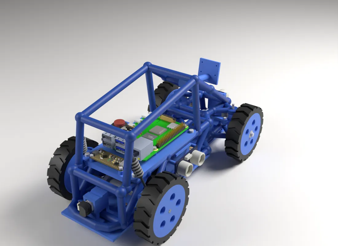
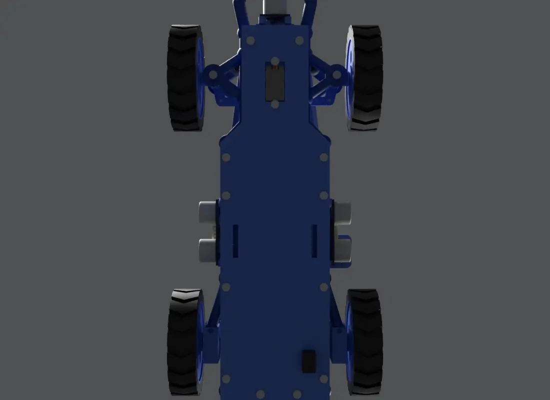
I built it like a buggy, from 8 mm printed tubes in dark blue PETG, which takes a crash better than PLA. Two flat side frames, 64 mm apart, hold the rails, the roll-hoop posts and the braces. Seven straight cross tubes join them, each cupped onto the frames' balls with an M3 screw at each end. A one-piece nose narrows to 40 mm between the front wheels and carries the A-arms, the servo and the bumper. Underneath, a 3 mm floor pan 15 mm off the mat holds the drive, the battery and the power boards; on top, a deck holds the Pi and the Metro Mini. The roll hoops rise to 132 mm, so they land first if the car rolls.
The wheels are 72 mm, on a 180 mm wheelbase and a 120 mm track, held out on double A-arms at the front and two trailing links to each rear hub. The coil-over shocks are only for the look. A flat mat needs no suspension, and leaving it out keeps the steering and the odometry exact. The printed parts follow the Roboticscool palette: dark blue #1B469E for the frame, arms and bumpers, and main blue #5280E2 for the rest.
The first car had a solid rear axle. In a tight turn one wheel had to scrub, and in the simulator the encoder then read up to 80% more than the car moved, which wrecked the position estimate. A LEGO Technic differential (62821), as KMIDS-GFM used, lets each wheel roll at its own speed. The rules allow it: 11.3 and 11.13 ask for one driving axle and no motor per side, and 11.5 rules out only an electronic differential. A printed 12-tooth bevel on the motor drives the differential's 28-tooth ring, and a LEGO 8L axle runs out to each wheel. With the encoder on the motor, before the differential, it measures the car's centre line to within 1% at any steering angle.
- 12 V gearmotor69%
- 6 V 50:1 motor25%
I sized the motor from torque and speed rather than picking the first one. Pololu rates the 12 V HPCB 30:1 at 1100 rpm and 0.39 kg·cm at stall, but a 7.4 V pack gives it only about 38% of its rated power. The 6 V 50:1 (#5187) gives 650 rpm and 0.74 kg·cm. The firmware divides by the measured pack voltage so the motor never sees more than 6 V on average, which keeps it in its rating as the pack drains. Through the 12:28 bevel the car does 1.05 m/s free-running.
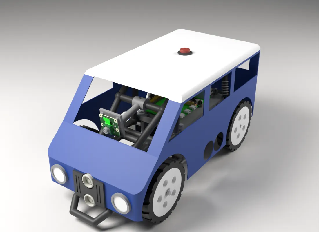
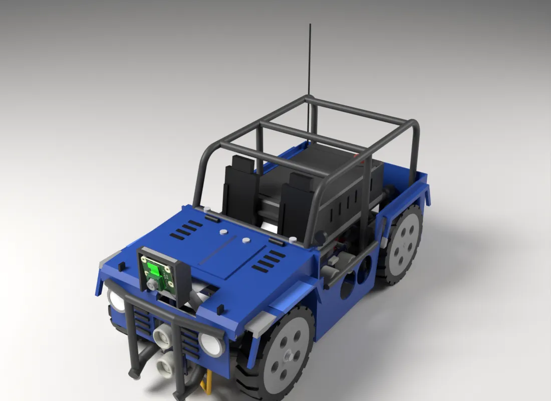
Narrowing the car to fit the parking lot
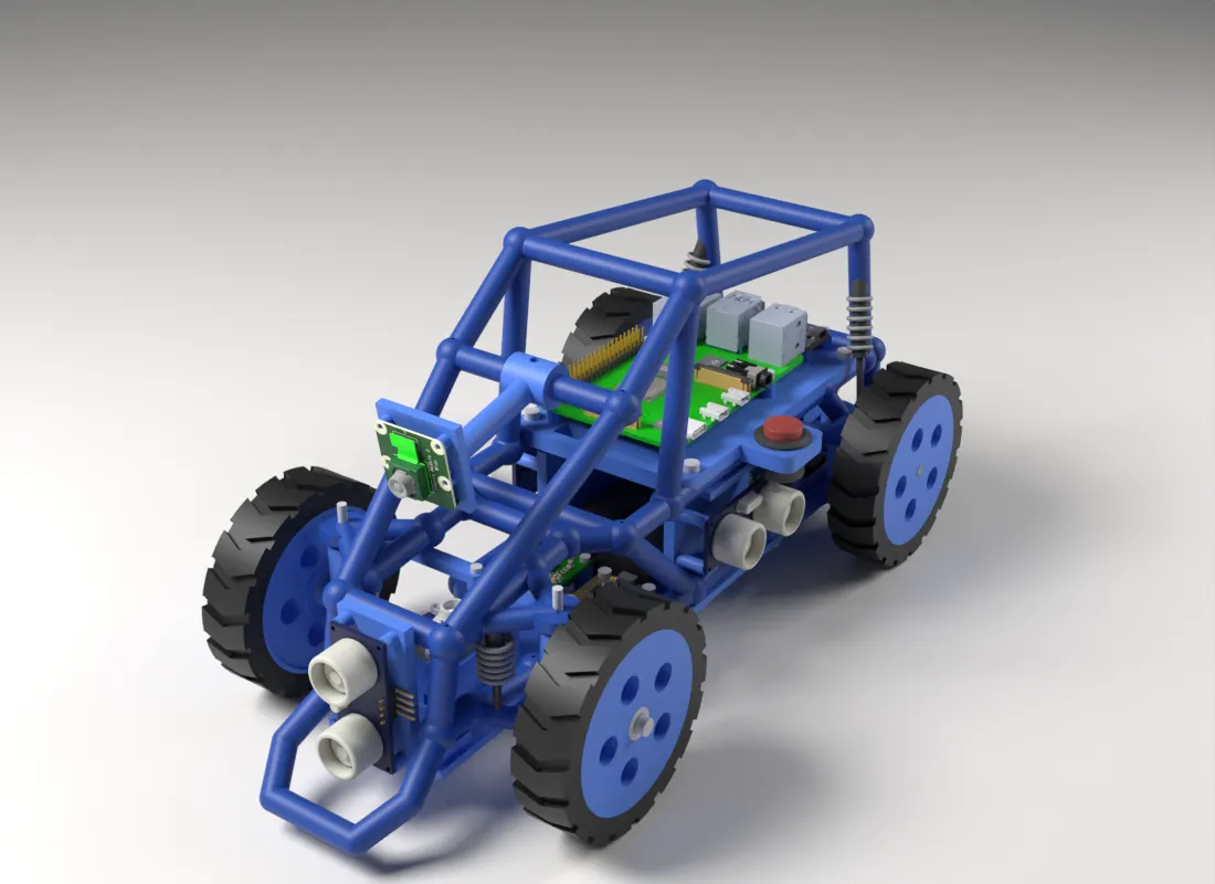
The parking lot is 200 mm deep, and a car counts as parked only if it is wholly inside and parallel to within 2 cm. My first buggy was 196 mm wide: legal, with 2 mm to spare on each side.
I let the parking planner decide the width. It searched for manoeuvres into the lot at each width I tried:
- First buggy196 mm
- Tried164 mm
- Final car143 mm
Narrowing also freed room to steer. The thin nose leaves space for the front wheels to swing in beside it, so the lock rose from 25° to 36°; at full lock a tyre's rear-inner corner comes to 29 mm from the centre line. An MG90S metal-gear servo drives two tie rods from one pin on its horn. The steering arms point at the rear axle's middle, which gives Ackermann geometry. Move the horn below to see the linkage the CAD solves.
Steer it
The inside wheel turns more, so both wheels roll round nearly the same centre. The thin lines are each wheel's axis; where they meet the rear axle line is where that wheel wants to turn about. At full lock the linkage reaches 78% of ideal Ackermann and a 283 mm radius.
The car as built in CAD: 28.5 mm each side. The planner found manoeuvres into the lot at 144 mm, so the car was narrowed to 143.
| Servo horn | Left wheel | Right wheel |
|---|---|---|
| +12° | +11.4° | +10.9° |
| +24° | +23.5° | +21.2° |
| +36° (limit) | +36.6° | +30.7° |
The build123d script that writes every STL also checks the assembly. No two parts may overlap at rest, and nothing may collide anywhere from −36° to +36° of steering, in 6° steps. Nothing may sit in the camera's view or in a sonar's beam, taken as a 15° cone out to 300 mm. The first narrow layout failed 21 checks.
The front sonar no longer fitted between the nose rails
It stands on end on a narrower bracket, and the bumper drops below its beam
Tie rods hit the balls where the A-arms meet the nose
The nose's upper rails rose 2 mm
The motor saddle crossed the rear cross tube
The saddle bridges the tube
Boards and the start button stuck out of the narrower frame
They moved in; the button sits on a tab off the deck
Wiring a camera, three sonars and one battery
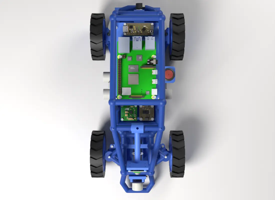
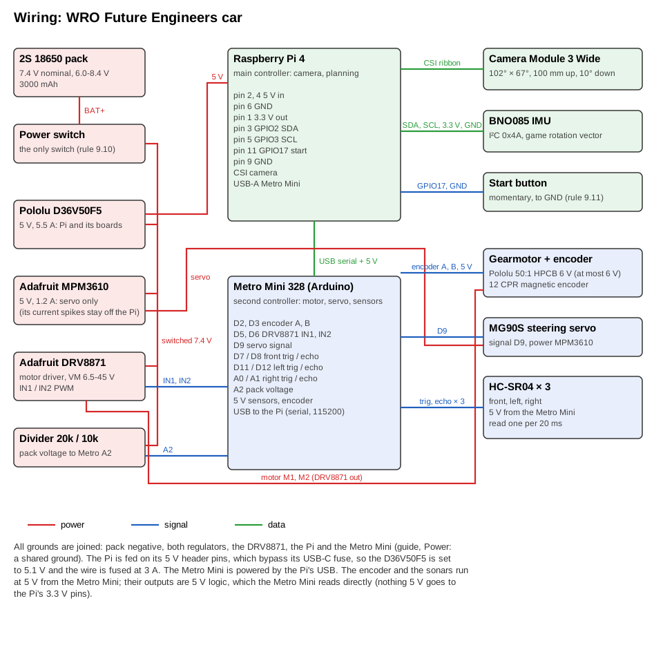
The guide suggests separate supplies for the controllers and the motors, but rule 9.10 allows only one switch. And Linux on a Raspberry Pi can pause for tens of milliseconds, which is long enough to miss encoder counts or leave a motor running into a wall.
A slow frame on the Pi then costs one steering update, never a lost count or a runaway motor.
I split the work between two controllers. The Pi runs the camera and makes the decisions. A Metro Mini runs everything that can't wait: the encoder counts, the speed loop, the sonar timing and the safety stop. A slow frame on the Pi then costs one steering update, never a lost count or a runaway motor.
- DeviceCameraModule 3 Wide320 × 180, 102°
- CodeRaspberry Pi 4vision, map, plan~40 loops a second
- CodeMetro Minispeed loop, sonarsreports every 20 ms
- OutputMotor and servodrive and steering
USB serial at 115200 baud; if the Pi goes quiet for 250 ms, the Metro Mini stops the motor
Power comes from one 2S 18650 pack (7.4 V, 3000 mAh) through one switch, split into three branches. A Pololu 5 V, 5.5 A regulator feeds the Pi and everything it powers. A separate 1.2 A regulator feeds only the servo, so its current spikes can't reset the Pi. The DRV8871 motor driver runs straight from the pack, and all grounds are joined.
| Load | Average | Peak |
|---|---|---|
| Pi 4 with camera and OpenCV | 6 W | 7.5 W |
| Metro Mini, sonars, encoder, IMU | 0.5 W | 0.5 W |
| Servo (MG90S) | 1 W | 3.5 W |
| Motor, held to 6 V | 1.8 W | 9 W |
| From the pack, after regulators | about 10 W, 1.4 A | about 22 W, 2.9 A |
No single sensor sees everything the car needs. The camera can't see a wall right beside the car, and the sonars can't tell a red pillar from a green one, so I placed them to cover each other's gaps.
| Sensor | Where it sits | Why |
|---|---|---|
| Camera Module 3 Wide | 100 mm up, tilted 10° down, on a boom over the front axle | At wall height it sees almost nothing past the walls, so judges and spectators don't confuse it. A 4:3 frame cut the view to 82° and missed a sign 45–60° to the side, so it runs 320 × 180 from the sensor's full-width mode. |
| Three HC-SR04 sonars | Sides 42 mm up; front one stood on end in the nose, 39 mm up | The side ones keep the car off a wall the camera can't see. The Metro Mini fires one per 20 ms cycle, so they never hear each other's echo. |
| BNO085 IMU | On the deck | Counts turns and holds heading. Its game rotation vector ignores the magnetometer, so venue steel and the motor's magnet can't pull it. |
| Motor encoder | Before the differential | 1400 counts per turn, 0.16 mm per count, measured along the car's centre line |
Calibration has a fixed order, written down in the repository: servo centre first, then the steering scale against the CAD table, distance per encoder count over 2 m of mat, the colours under the venue's light, and the speed loop last.
Driving the open challenge on walls and heading
In the open challenge the inner walls move between rounds and the car doesn't know which way round it will go. A fixed route can't work, so the car has to read the track every lap.
I gave the car three jobs at once. It centres between the walls by comparing how much wall fills the left and right of the camera frame. The side sonars take over within 180 mm of a wall. The IMU holds the straight's heading. The first corner line it sees sets the direction: orange first means clockwise.
Regions of interest
One region per job: the walls to the left, right and ahead, and the floor just in front for the corner lines.
Blur
A 5 × 5 blur takes out the mat's speckle before any colour test.
Threshold in HSV
One range per colour, kept in
config.pyso the venue's light can be re-measured in minutes. Red wraps round hue 0, so it has two ranges.Contours and centroids
Each blob's centre comes from its image moments. The guide shows a 160 × 120 frame loses the corner lines, so the car works at 320 × 180.
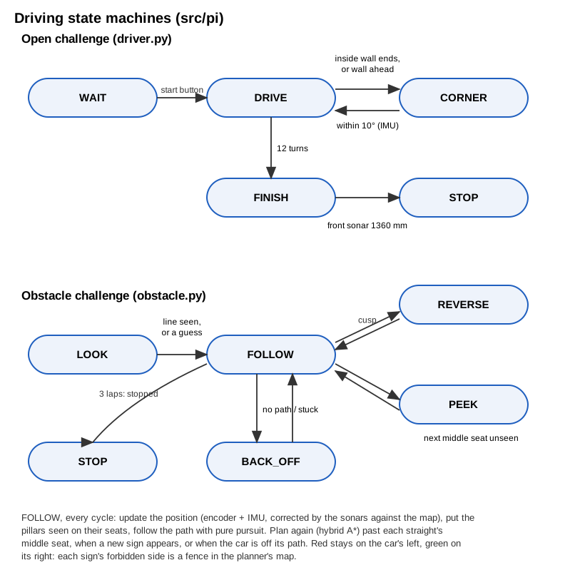
The diagram shows the states; the log shows why the car moved between them. Step through field 1, driven clockwise, at the moments it changed state, with the sensor readings it had and the line of code that fired.
Open challenge · field 1, clockwise · src/pi/driver.py
01 / 08 · log time 0.00 s
Waiting in the start zone
The motor is off and the program is running. Only the start button moves the car out of WAIT.
if start_pressed:
    state = "DRIVE"
target_heading = heading- Front
- 1110 mm
- Left
- 747 mm
- Right
- 127 mm
- Heading
- 0.0°
Planning a path past the signs
Reacting to the nearest pillar works on the walls, and it failed on the signs. A sign can sit right where a corner ends, and by the time the camera sees it the car is already in the wrong lane.
If a corner was undrivable, no software would fix it and I'd need a different car.
Before writing any obstacle code I checked the geometry. A path search over a kinematic bicycle model tried every corner the 36 sign cards can produce, from both directions, staying on the legal side of every sign. If a corner was undrivable, no software would fix it and I'd need a different car.
- 261
- corner cases, all drivable forward at 25° of lock
- 36°
- of lock available, so 11° in hand
- 4 of 20
- start-straight cases need a short reverse, which rule 9.21 allows
So a failure in the simulator would be the code's, not the car's. I replaced reacting with planning, using the textbook methods from the RoboRacer (F1TENTH) course, cut down to fit a WRO track.
First version: react
- See the nearest pillar
- Steer round it
- Too late for a sign at a corner exit
Now: plan
- Map every sign it has seen
- Search a path it can drive
- Follow it, and plan again when something changes
- CodeLocateencoder + IMU, sonar beams cast at the walls10–20 mm in sim
- CodeMap signspillar base projected to the floor, snapped to a legal seat
- CodePlanhybrid A* over arcs it can drive, a fence on each sign's wrong side
- OutputFollowpure pursuit150 mm look-ahead
new sign, a straight's middle seat, or 130 mm off the path
Where am I?
Odometry is the encoder's distance along the IMU's heading, and it drifts. So every sonar reading is compared with what that sonar should hear from the estimated pose, by casting its beam at the walls, the known signs and the parking blocks. An HC-SR04 hears a wall within about 15° of square, and a ray more than 22.5° off a surface is lost. The difference nudges the estimate.
Where are the signs?
Each pillar's base is projected to the floor through the camera's 100 mm height and 10° tilt. Far away, the camera gets a sign's bearing right and its range wrong, so the car decides the slot first and waits until it is close to decide the row, 400 or 600 mm from the outer wall. Until then the planner keeps clear of both.
Which path?
Hybrid A* over position and heading, on arcs the car can drive. Each sign is a 50 mm box with 20 mm of clearance, plus a fence to the wall on the side it mustn't be passed, so no path can pass red on the wrong side. Each plan runs to wholly past the next straight's middle seat, already in the lane the next sign needs.
What if it can't see?
If the next straight's middle seat hasn't been seen, the car stops at the entrance, centred, and looks before planning on. This happens in lap 2 at the start straight, whose far seats are out of view in lap 1.
Which way round?
From the first corner line. From the start zone a line can be a metre away and a pixel high, so if none shows in half a second the car guesses. A wrong guess just mirrors the map, because “red on my left” is the same rule either way.
How fast?
Plans take 10–300 ms on a laptop, about five times that on a Pi 4. Laps 2 and 3 reuse lap 1's plans from the same poses.
Here is field 1 from start to finish, the run in the video at the top. The pose comes from the referee script; the state, sonar readings and steering come from the car's own log, matched by its position estimate. Scrub, press play, or jump to a moment.
Referee time 17.3 s · lap 1 of 3
Following the plan
pure pursuit, 150 mm look-ahead, re-planning as signs appear
- Front sonar
- 1061 mm
- Left sonar
- 571 mm
- Right sonar
- 326 mm
- Speed
- 281 mm/s
- Steering
- +16.0°
- State
- FOLLOW
Leaving the lot took about 16 seconds of short moves, so lap 1 closed at 38.8 s. Laps 2 and 3 took 24.2 and 24.8 s, with every sign already on the map.
Parking in a lot 200 mm deep
The lot is worth 22 of the 62 points, and it is the tightest place on the track: a gap between two blocks, 200 mm deep, with a sign seat in the corridor beside it whose colour the car can't know at the start. Touching a block ends the round.
I searched for the manoeuvres once, on a computer, and stored them, because the rules fix where the lot sits in the start straight. On the mat the car only has to reach the first pose of a stored path and follow it. Pick a manoeuvre and drag through it.
The start straight, anticlockwise · src/pi/park_paths.json · 1 unit = 1 mm
Point 1 of 85 · 12 mm apart
Move 1 of 11 · start pose
0.0° off parallel to the wall
At the start one side sonar reads the wall about 50 mm away and the other reads far, so the car knows it is in the lot and which way round to go.
The search ran once, on a computer, with the same hybrid A* as the corners: reversing allowed, 24 mm steps, 12 mm from the blocks. It stored 33 ways in anticlockwise and 54 clockwise.
The moves are a few centimetres long, too short for pure pursuit, so the car steers from each point's own curvature, corrected for offset and heading. Reversing, the linearised dynamics show the offset term keeps its sign and the heading term flips. It slows into each change of direction and waits there until the servo has swung across. In the lot it shuffles at full lock, forward one way and back the other, until it is within 2.5° of parallel, where the rules allow about 6°, and never closer than 10 mm to a block.
Testing the car's own code in Webots
With no car on a mat, bench tests could check each piece but not whether the pieces add up to three laps and a parked car. That needed a full round, scored the way a judge would score it.
Bench tests could check each piece but not whether the pieces add up to three laps and a parked car.
I built a Webots simulator that runs the car's own vision.py and driver code, unchanged. The buggy there is the CAD model, split into its six rigid bodies with their meshes, masses and centres of mass, and the camera and sonars sit where the CAD puts them. The fields come from the 2026 rules' figures: six sign seats per straight, the 36 cards, corner lines at 30° and 60°, die-rolled start zones and the lot on the section's dotted line. A referee script scores each run by sections 9–10 and appendix A. The simulated Pi runs five times slower than my computer, and the Metro Mini's watchdog stops the motor while it is busy, so slow planning costs the car real time, as it would on the mat.
| Challenge | Fields | Result |
|---|---|---|
| Open | 8 random, both directions, both corridor widths | 30 / 30 on all eight, 56–62 s |
| Obstacle | 20 random, both directions; 12 used while tuning, 8 never seen | 62 / 62 on all twenty, 100–152 s |
Seconds from the start · 100.3–152.3 s · every run full marks
Field 1, anticlockwise: laps done at 38.8, 63.0, 87.9 s, then 19.8 s of parking. 62 / 62 in 107.7 s.
Getting there took bugs the bench tests hadn't caught. The simulator found five:
- The sign rule was backwards, keeping red on the car's right.
- Early turns clipped narrow inner walls.
- Slipping wheels inflated the corner count.
- The stop point drifted with lap distance.
- A car stuck on a wall had no way out.
Fixing them took, in order: a map of the signs and a planner instead of reacting; ray-cast sonar corrections; telling a sign's slot from its row; the full-width camera frame; the narrower car with a differential and more lock; and stored manoeuvres for the lot. The bench tests now cover each vision output on drawn frames, the serial parser, three made-up laps of the open challenge, backing off a wall, the sign rule both ways round, the camera's floor projection, the sonar model and the stored manoeuvres.
| Risk on the day | What's done about it |
|---|---|
| The Pi crashes mid-run | The Metro Mini stops the motor 250 ms after the last command |
| The pack sags | Motor voltage is computed from measured pack voltage; the motor stops below 6.8 V |
| The venue's light is different | Every colour range is in one config file; a probe tool re-measures in minutes |
| The corner count is wrong | IMU turns and corner lines check each other; the stop comes from measured distance |
| Printed parts come out loose or tight | Print test pieces of the bearing seats, motor saddle and servo pocket first |
Turning the CAD into a booth game
A car that exists only in CAD and a simulator is hard to show at a booth, and visitors can't try it.
I made WRO Build and Drive ↗, a short VR game. You assemble the car from its own CAD parts, then race one lap of a WRO field against the robot. It runs in a browser, with arrow keys or WASD, and on a Quest.
Build
Red button: 11 parts, about two minutes. Blue button: the whole car in 147 steps, in the order the build planner chose.
Race
One lap, anticlockwise. Red pillars on your left, green on your right.
Result
Your time plus penalties, against the robot's.
- 24.7 s
- the ghost car's lap: the robot's own path from Webots
- +2 s
- hitting a wall
- +5 s
- knocking a pillar over
- +5 s
- passing a pillar on the wrong side
Notes
- The car has not been built or driven on a real mat. The photos are renders, and the driving videos the rules ask for are still to film.
- The colour thresholds are starting points, to be measured under the venue's light, and the turn-scrub correction is set to zero until it can be measured on the mat.
- In 9 of the 20 obstacle runs the referee script logged a wrong-side pass on the way into the lot, just before lap 3 closed, and didn't count it. That follows the repository's reading that sign sides stop counting once the car heads to park; the appendix A.5 text doesn't say so in as many words, so it needs confirming with a judge.
- The latest CAD check looks for fasteners too, and lists 34 parts the model doesn't yet show held by a screw, strap or tie.
- The VR game has not been tried in a headset yet.
Sources
- WRO Future Engineers ↗, World Robot Olympiad Association: age group, team size, size limit.
- WRO Future Engineers 2026 General Rules: track, round length (9.1–9.2), scoring (10.2), appendix A.
- Future Engineers Getting Started guide ↗: camera height, steering, vision steps.
- WRO engineering repository template ↗.
- RoboRacer (F1TENTH) ↗ course: ray-cast sensor model, hybrid A*, pure pursuit.
- KMIDS-GFM, WRO Future Engineers 2025 engineering repository: differential drive, starting in the lot.
- Pololu HPCB gearmotor datasheets: stall torque and the 25% continuous-load advice.
- Webots ↗, the open-source robot simulator the runs above come from.